NavList:
A Community Devoted to the Preservation and Practice of Celestial Navigation and Other Methods of Traditional Wayfinding

Re: Centerless Sextant
From: George Huxtable
Date: 2008 Jul 2, 10:48 +0100


From: George Huxtable
Date: 2008 Jul 2, 10:48 +0100
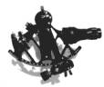
There are a few more things to say about the centerless sextant, last
touched on in my posting [5617].

There, I had speculated, about the use of a wide-angle prism in the place of
a horizon mirror-

"As far as I can see, it allows the
reflected light ray to be displaced vertically, so allowing greater spacing
between the index mirror and the telescope. However, that spacing is far
more than really needed to accommodate the telescope that's shown, but it
might then allow the substitution of a larger-aperture telescope, for night
vision."

On second thoughts, however, fitting such a larger-aperture telescope would
be impossible for another reason. It has to fit into the gap between the
main back-plate and the carrier, which must pass over it. Even with the
small telescope shown, the clearance provided in the drawing doesn't seem
adequate; a larger one would be impossible.

===========================

Some other points-

The division, in the field of view, between direct and reflected images, is
a horizontal line (at the lowest edge of the prism), and not a vertical line
as in the normal sextant. That looks particularly awkward, seeing that you
have to put the horizon on that same line, and could make index-error
checking difficult. Some very early reflecting quadrants were designed that
way, but the design soon changed to a vertical split between the two images,
for good reasons. Could an observer easily get accustomed to that horizontal
split, I wonder? Perhaps it would cause no difficulties in measuring
horizontal sextant angles, which I have speculated migh be its intended
purpose, and which might also explain the shortage of shades (below).

===========================

Two shades are shown, and from what I can make out, both are intended to
obtrude into the reflected light path, one into the upper half of the
horizon-prism, the other into the lower, but both into that same path. So
there appears to be no provision for putting any shades into the direct
horizon-path, as is standard provision on a normal sextant.

============================

An adjustment is provided, with a slot and screw, for pivoting the mounting
of the telescope, and two contradictory explanations are given. On page 2,
line 36, it explains that it can be used to adjust the relative amounts of
light entering the telscope via the two paths, which seems reasonable. It
fulfils, then, the same purpose as a "rising piece", to be found on many
conventional sextants. However, on page 1, line 48, it explains that this
adjustment acts to correct collimation error. To me, this seems wrong. No
adjustment allows for tilt of the telescope, towards or away from the plane
of the frame, which is what collimation error requires.

============================

In my last message, I wrote-
"There appears to be a silly error on page 2 of the patent's text , line 27.
It describes, sensibly, in line 31, the pitch of the screw as being equal in
pitch to a 720th of a circle, so that one revolution of the spindle moves
the carrier half a degree. But then, it goes on to say "To enable readings
to be taken of less than half a degree the head f4 of the spindle is divided
into 30 divisions ..." continuing, to say that these could be further
subdivided. But of course, that spindle-head should be divided into 60
minutes, just like the drum of a normal sextant, because the carrier
movement of half degree changes the viewed angle by 1 degree.."

but in writing that, I had missed another curious statement. Those words
were immediately preceded by-

"The limb "a" is marked in degrees and half degrees of a circle....", which
of course would be inappropriate for a reflecting instrument with a
screw-pitch of one 720th of a circle. It should be marked in whole degrees
of reflected angle, corresponding to each turn of the screw; and indeed,
from the drawing, that's how it actually seems to be marked. But from a look
at the drawing, the drum appears to have been (wrongly) marked in 30
divisions, just as (wrongly) described above.

I wonder if the arc and micrometer were originally intended for some sort of
non-reflecting instrument, such as a theodolite, which has given rise to
that confusion in the patent application?
.
George.

contact George Huxtable at george@huxtable.u-net.com
or at +44 1865 820222 (from UK, 01865 820222)
or at 1 Sandy Lane, Southmoor, Abingdon, Oxon OX13 5HX, UK.


--~--~---------~--~----~------------~-------~--~----~
Navigation List archive: www.fer3.com/arc
To post, email NavList@fer3.com
To , email NavList-@fer3.com
-~----------~----~----~----~------~----~------~--~---