NavList:
A Community Devoted to the Preservation and Practice of Celestial Navigation and Other Methods of Traditional Wayfinding
Azimuthal equidistant grid
From: Andrew Nikitin
Date: 2009 Sep 29, 18:23 -0700
From: Andrew Nikitin
Date: 2009 Sep 29, 18:23 -0700
I thought of a modification of a known method of approximate graphic solution
of spherical triangles. It involves plotting points on a grid that resembles a
grid of parallels and meridians.
Similar method was mentioned by Gary Lapook in
http://www.fer3.com/arc/m2.aspx?i=108398&y=200905
The referenced ARG1 device uses equatorial aspect of stereographic projection.

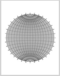
I made similar grid, but for equatorial aspect of azimuthal equidistant
projection. It has the benefit of having angular distance from center of grid
to any other point be simply linear distance. If one chooses scale 1 degree=1mm
(which I did), the angular distance can be measured with a regular mm rule.
Also, by freak coincidence, grid of 18 cm diameter has just the right size and
fits on a sheet of paper comfortably.

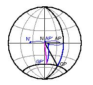
As an example, I will explain how navigational triangle can be solved using this
method. (see picture)

Let's have both GP and AP in northern hemisphere. AP is 52N, GP is 25N, LHA is
61 degree.
In the beginning the center of the grid represents the north pole, outside
circle is equator and right half of horizontal line -- is the meridian of AP.
Let's mark the AP at on the meridian 90-52=38 mm from pole (or 52mm from
equator). Then mark GP on the line 61 degrees down from meridian and 65mm from
pole (or 25 mm from equator). These are points on a celestial sphere and they
are projected on the grid. Now we rotate the sphere along the meridian until
AP moves to the center of the projection. Both N and AP move to the left
28mm.
AP ends up in AP', in the center of the grid, N moves to N'.
Now GP also move 38 degrees along one of the "horizontal" curved lines that
look like parallels. GP ends up in GP'. Alternatively, GP may be projected on
the horizontal line along one of the "vertical" curved lines, then moved along
horizontal line 38 mm to the left and then returned to its original "latitude"
along another "meridian" line. The transition along the horizontal line may be
peformed with a dividers or a rule.
Now with AP in the center we can measure distance from AP to GP with a rule (or
select it with a dividers and then transfer this distance to a horizontal or
vertical line, which are both subdivided into 1 degree=1mm intervals). The
azimuth or may be also read directly as angle beween N and GP along the limb.

Different triangles can be solved in a similar way. The idea is to construct
the triangle by bringing points to the center using suitable combination of
rotations along the vertical axis and along the center and constructing other
points that are in relation with the central point using the fact that
distances and angles from the central point can be measured directly.

I noticed that different printers handle thin lines differently and I could
not figure out the thicknesses of lines that look good on all printers.
That is why i include original postscript file. The line thicknesses can be adjusted in the
/LW [0.1 0.3 0.5] def
These are points (=1/72")

Andrew Nikitin


--~--~---------~--~----~------------~-------~--~----~
NavList message boards: www.fer3.com/arc
Or post by email to: NavList@fer3.com
To , email NavList-@fer3.com
-~----------~----~----~----~------~----~------~--~---
File: 109992.grid_azeq.zip
