NavList:
A Community Devoted to the Preservation and Practice of Celestial Navigation and Other Methods of Traditional Wayfinding
From: David Pike
Date: 2017 Apr 10, 14:25 -0700
I’ve now had the Kollsman periscopic mounting that I irreverently named the ‘Sports Model’ for a couple of days and have had chance to examine it. It’s absolutely brand new and looks as if my Kollsman periscopic is the first to ever go inside it.
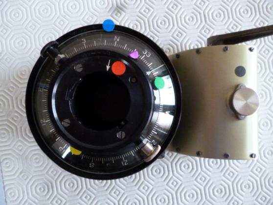
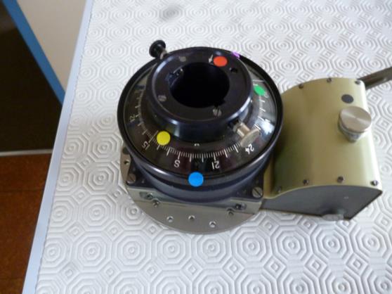
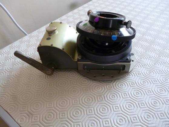
Its Type No is: 1287 M-01, and its Serial No is 1328, so clearly it’s not a ‘one-off’. However, I’ve been unable to find very much detail about it using Google, which is strange, so I’ll describe it and how I believe it should be used in detail here. The dot colours refer to the coloured dots I stuck on before taking the photographs. I’ve used Kollsman allocated part names where available from the installation instructions which came the mounting. Names followed by an asterisk are names I’ve chosen.
We begin with the top half of the mounting (black dot). This looks like that of a standard Kollsman ‘winder’ mounting. There is no provision for electrical power and therefore no heating or lighting in the mounting itself. The ‘sextant holding tube’* (red dot) is free to rotate with the sextant unless the ‘line of sight locking lever’ (purple dot) is applied. The sextant holding tube has a white arrow etched on it (next to the red dot). This is to aid correct insertion of the sextant. There is a similar arrow on the sextant periscope, and the two should be aligned for the first part of sextant insertion. Fixed to the sextant holding tube is a clear plastic disc (green dot) with a white arrow marked on it (next to green dot). This white arrow always points in the same direction as the sextant line of sight and is called the ‘azimuth index line’. Below the clear plastic is the azimuth scale ring (blue dot), which is free to rotate and is turned by hand by holding the knurling on its outer edge. This ring has degrees etched upon it from 000 to 360. The numbers increase anticlockwise, so they’re correct when the mounting is upside down above the observer’s head. The friction between the azimuth scale ring and the main body of the mounting is strong enough to prevent it moving with rotation of the sextant. Between the azimuth scale ring and the sextant holding tube and locked to the main body of the mounting is another small ring, the ‘middle ring’* upon which is etched the ‘lubber line’ (next to the yellow dot). The position of the lubber line can be adjusted to the correct position when the mounting is first installed in the aircraft by slackening four hex headed screws behind the azimuth disc, but you would need a very long thin spanner and a great deal of patience and dexterity to accomplish this.
To find a star: 1. Set Hc on the sextant. 2. Ensure the sextant holding tube is unlocked. 3. Move the azimuth scale ring by hand until the aircraft’s indicated true heading is against the lubber line. 4. Move the sextant until the azimuth index line points to the star’s azimuth on the azimuth scale ring. 5. Identify the star, line everything up, and take the observation.
To finish with a heading check: 6. After the observation is completed, lock the sextant holding tube using the locking lever. 7. The azimuth index line will be displaced from the correct azimuth scale position by any heading error. 8. Move the azimuth ring by hand until the azimuth index line and the scale position line up again. 9. Read the aircraft’s real true heading against the lubber line. I wouldn’t recommend flicking the locking lever at mid-time, as you might with a Smith’s sextant, because the Kollsman sextant will no longer rotate to follow the star for the remainder of the observation.
The Azimuth pointer and a small portion of the azimuth ring and markings can be seen through the eyepiece of a pendulous reference model Kollsman as with the standard mount, but it’s more difficult to read and not really necessary, because you get such a good view looking directly at it. DaveP
