NavList:
A Community Devoted to the Preservation and Practice of Celestial Navigation and Other Methods of Traditional Wayfinding
From: UNK
Date: 2010 Jan 18, 03:59 -0800
I wrote back in July about my plan to make a working model of the HR-1
German model of the Bygrave slide rule using off-the-shelf items to make
the locking device that sets the HR-1 apart from the Bygrave. See my
prior posts at:


http://www.navlist.net/m2.aspx?i=109056&y=200907

http://www.navlist.net/m2.aspx?i=109993&y=200909

I have now accomplished my goal. I have attached twenty eight
photographs showing how to do this, but read my prior posts before going
further.

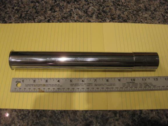
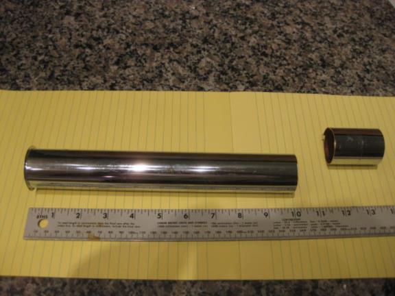
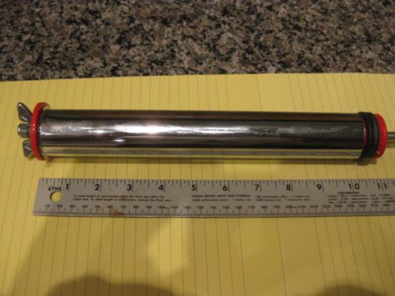
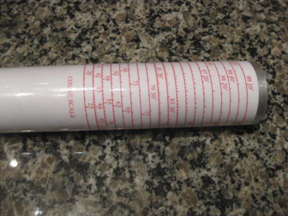
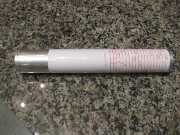
Going in numerical order, the first two photos show the 1.500 inch
outside diameter tube that I have used for my prior Bygrave re-creations
cut off to ten inches that will be used to mount the cotangent scale.

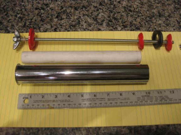
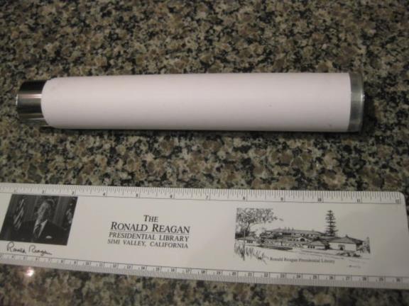
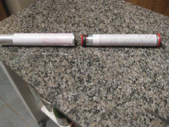
The next photo shows the locking mechanism I had described in my prior
posts along with the cotangent tube and a piece of PVC pipe cut to fit
inside the cotangent tube to take the compression load of the locking
mechanism.

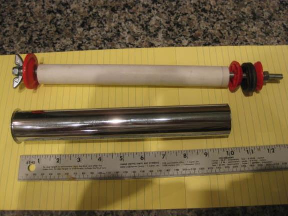
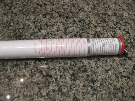
Photo four shows the locking mechanism with the PVC pipe in the
assembled position.

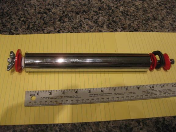
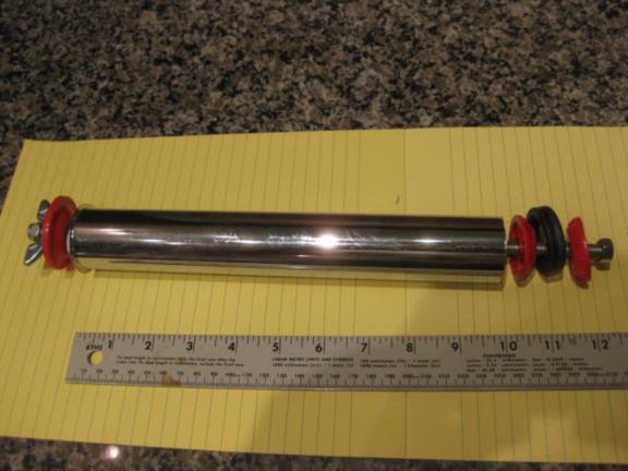
Photos five, six and seven show the same now installed inside the
cotangent tube.

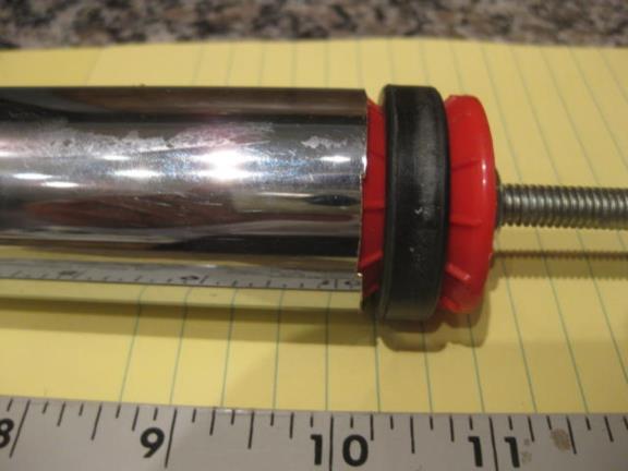
Photo eight shows a detail of the expanding ring that is used to lock
the two tubes together.

The difficulty in making this is finding tubes that are a good tight
fit. I found aluminum tubing used for making antennas at:

http://www.dxengineering.com/Products.asp?ID=278&SecID=136&DeptID=43

They have tubing with an outside diameter of 1.625 inches and a wall
thickness of .058 inches making the internal diameter 1.519 inches, a
good fit on 1.500 inch O.D. tubing. If you could print the cotangent
scale directly on the 1.500 tube this would be a good solution but my
method requires me to print the scale on paper and mount it on the tube
under a plastic sheet for protection making the diameter of the
cotangent scale 1.520 inches, too large to fit inside a tube of this size.

The next largest size of tubing in 1.75 O.D., 1.634 I.D., too large for
a good fit on the 1.520 diameter cotangent scale.

http://www.dxengineering.com/Parts.asp?ID=2413&PLID=278&SecID=136&DeptID=43&PartNo=DXE-AT1251

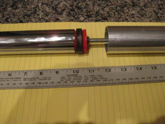
Photo nine shows this tubing in line with the cotangent tube.

Photo ten shows my solution to this problem. I decided to bush the inner
tube out to fit closely to the cosine, outer, tube. I used five sheets
of regular paper, 8.5 by 11 inches (standard paper size in the U.S.),
glued with rubber cement (which has the advantage, that if you need to
start over, the glue will come off easily) totaling 55 inches wrapped
around the tube. The paper is .004 inches thick and the five sheets
brought the diameter close enough (considering that the cotangent scale
and the plastic sheet would be placed around it) to make a good fit to
the cosine tube. Since I wanted to seal the scale from the environment,
prior to putting the paper on the tube, I used several sheets of the
sticky plastic sheets cut into 1/4 inch wide strips to wrap around the
tube near the top to bring the diameter out far enough that the plastic
sheet mounted on top of the scale would stick to these layers of plastic
thus sealing off the top of the tube and the scale. After mounting the
paper I did the same thing at the other  end of the paper this time
using 3/4 inch wide strips.

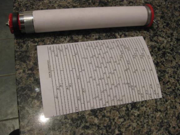
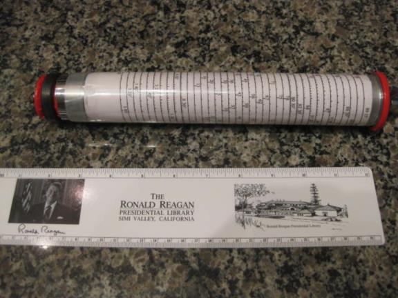
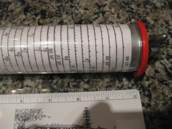
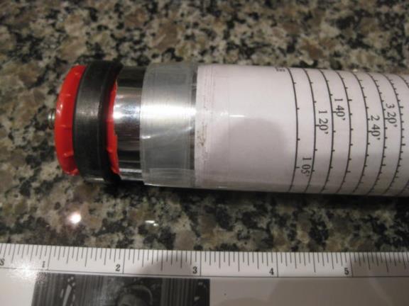
Photo eleven shows the cotangent scale and photo twelve, thirteen and
fourteen shows th scale mounted on top of the paper on the cotangent
tube and covered with the protective plastic sheet.

Photos fifteen and sixteen show the cosine scale mounted on the larger
tube and covered with a plastic sheet. Photos seventeen and eighteen
show the cotangent tube being inserted inside the cosine tube.


Making the cosine scale presented a bit of a problem. Since the cosine
tube has an O.D of 1.750 and the cotangent scale was only 1.520 inches
in diameter it was necessary to print the cosine scale at a larger scale
than the cotangent scale which was not a problem using Acrobat. However
when I tried out the scales a problem presented itself. My printer made
the cosine scale wider but also taller so that the pitch of the scales
no longer matched. Although it worked this way it caused ambiguity since
the cursor would sometimes end up between spirals on the cotangent scale
and either answer (higher or lower than the end of the cursor) could
have been the correct one. I contacted Dave Walden (the original source
for the scales I have been using) and he was able to modify the vertical
and horizontal ratios of the cosine scale so that, when printed out wide
enough to fit around the tube, the vertical spiral pitch matched the
cotangent scale. (Thanks again Dave.)

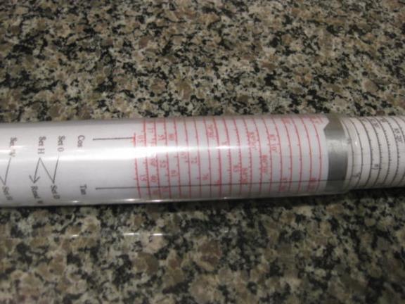
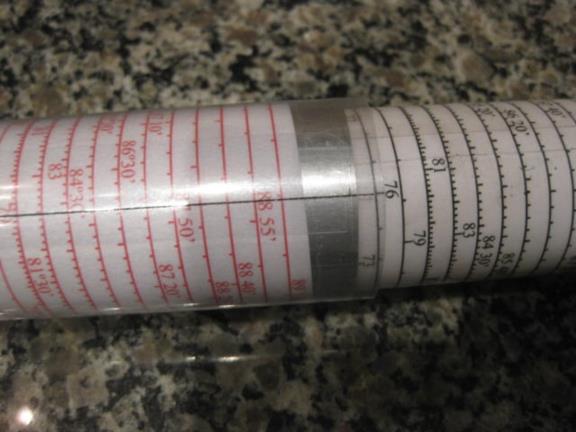
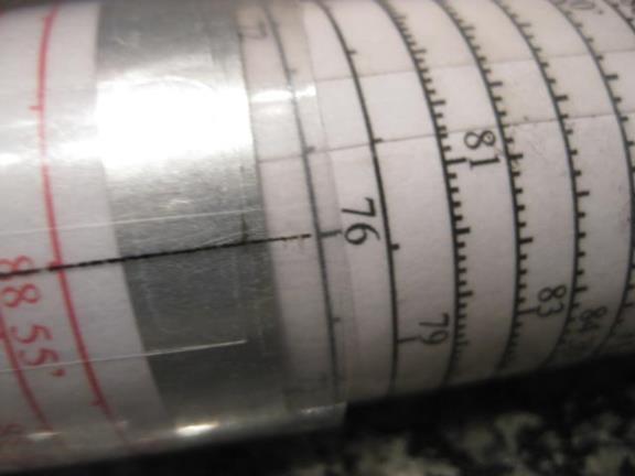
Photos nineteen and twenty show the two cursors, the cosine cursor
pointing to zero and the cotangent cursor on 76 degrees. I again made
the cursor  out of clear plastic by first printing the instructions on a
sheet of paper, drawing in the cursors and then photocopying this onto a
clear plastic sheet made for use in an ink jet printer. I then wrapped
it tightly around the cosine scale and held in that position with two
pieces of scotch tape on the inside of the cursor tube. I then wrapped a
sticky clear plastic sheet around it to protect the printing on the
cursor tube and to hold it in shape. I then removed the scotch tape.

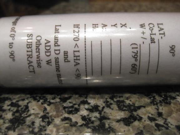
Photo twenty-one shows the condensed instructions printed on the cursor
tube. The cosine scale is white underneath this section of the cursor
tube to enable easier reading of the instructions.

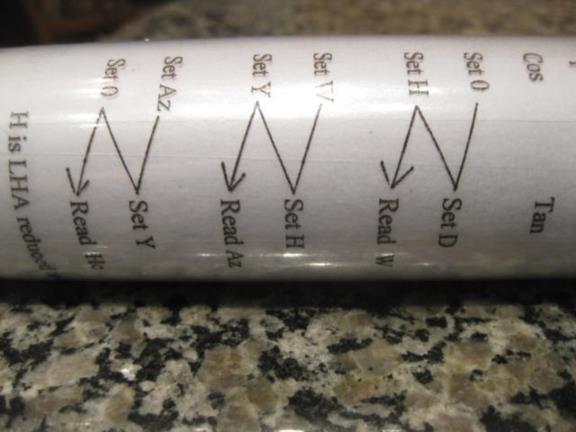
Photo twenty-two shows the "zig-zag" printed on the cursor tube which
lines up with the two cursors to guide the user through the computation.

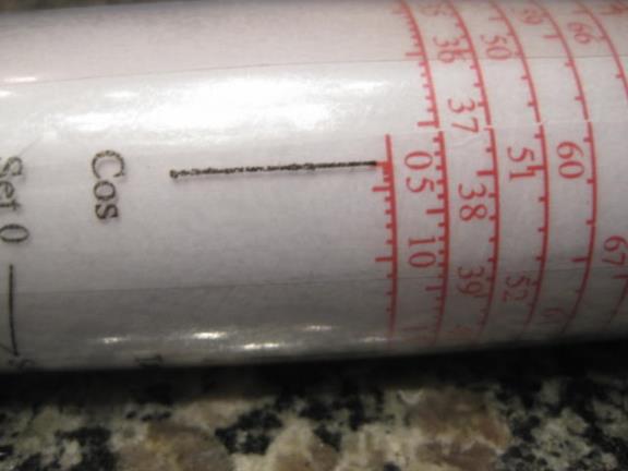
Photo twenty-three and twenty-four show close ups of the cursors
pointing to zero on the cosine scale and 76° on the cotangent scale.

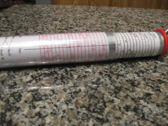
Photo twenty-five shows the cursor pointing to 76°on the cotangent scale.

Photo twenty-six shows the tubes extended so that the cotangent cursor
can point at 55'.

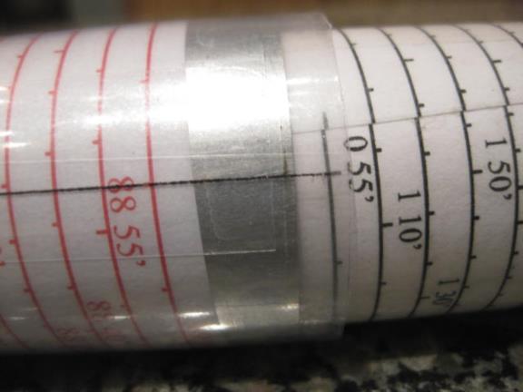
Photo twenty-seven shows a close up of the cursor pointing to 55' at the
bottom of the cotangent scale.

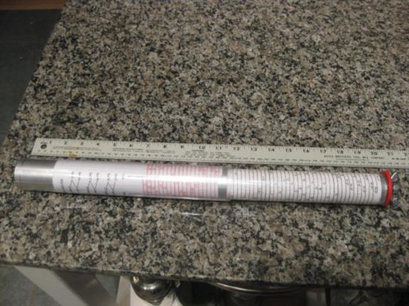
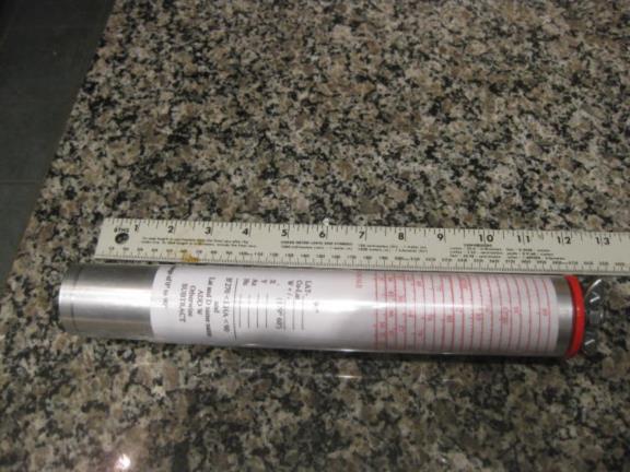
Photo twenty-eight shows the tubes collapsed.

Turning the wing-nut (control knob) one quarter of a turn locks the two
tubes together and is an easy manipulation to make. Since the cosine
tubing is only .058 inches thick the cosine scale and the cotangent
scale are very close together, and to the cursor, minimizing any
parallax problem when reading the scales.

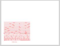
I have also attached the modified cosine scale and note that the tick
marks go down from the line under the numbers. The cotangent scale is
made with the scales posted last March bt Dave Walden for the flat
Bygrave at https://navlist.net/img/107501.f2-lapook1.pdf

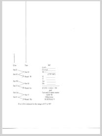
Also attached is the form for the cursor tube.

The only downside to this model, compared to the prior model I made of
the Bygrave, is that it is three times heavier since the locking
mechanism and the cosine tube each weigh as much as my original
re-creation of the Bygrave.

I demonstrated this HR-1 to Frank, Mike and Greg prior to our flight
last Saturday.
gl
