NavList:
A Community Devoted to the Preservation and Practice of Celestial Navigation and Other Methods of Traditional Wayfinding
Re: The backstaff. was: Re: The Shovell disaster
From: Nicolàs de Hilster
Date: 2007 Nov 07, 10:24 +0100
From: Nicolàs de Hilster
Date: 2007 Nov 07, 10:24 +0100
To keep it simple I will answer NavList 3755 & 3810 (Michael Daly) and
3812 (George Huxtable) in this single post.

In Navlist 3755 Michael wrote:
> Circular arcs require circular
> transversals to be accurate.  However, it was difficult to figure out
> how to construct them (one technique was determined by Philippe de La
> Hire and used by Nicolas Bion) and very tedious to construct (I have
> created a diagram of linear transversals on Wikipedia but have yet to
> tackle the effort of making a circular transversal diagram - yet I have
> the advantage of a CAD program, not a sheet of brass with dividers and
> compasses).
So far I did not yet answer to this correctly, so I will give it a try:
There are two ways to construct those diagonals:
1) Using a tilted cutting plate (I think that is how they were constructed)
2) Using a very long beam compass

And now in detail:
1) Using a tilted cutting plate (I think that is how they were constructed)
When I make the diagonal scales I use a beam with a cutting plate along
which I cut the lines of the scales. The position of the beam is
controlled by a series of holes along an arc outside the actual scale
(the instrument is fixated on a board on which that arc is). I start out
with the perpendicular line as those are the easiest. Then the
concentric lines are drawn and small marks are made on the first and
last concentric circle to indicate the positions of the 10 arc minute
intervals. Not all 10 arc minute intervals are marked, just a few of
them. The divisions of the whole 5 degree marks are drawn as well. Now
the cutting plate is tilted using two adjustment screws until it fits
the small marks that I made before. With the cutting plate in the proper
direction I can mark of the diagonal scale in the smae way as I did the
perpendicular scale.

2) Using a very long beam compass
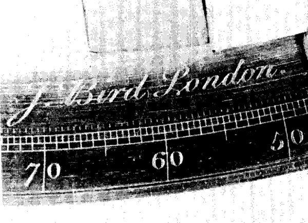
John Bird left us some instruments on which can be seen that the degree
marks were cut using a beam compass, a method that could be applied on
making diagonal scales as well (see attached picture, sorry for the
quality, it comes from ION Vol. 34, No.2, /Moskowitz: World's First
Sextants/). Clearly can be seen that the divisions are curved and that
the centre of the beam was on the left.
In his book '/Taking The Stars/' Peter Ifland says "...a more accurate
construction required that the diagonals be arcs of a circle passing
through the point where the diagonal crossed the base line of the scale
and the center of the instrument." (p. 52). This method too is just an
approximation of the problem as the diagonals are no arcs but clothoids.
On the W. Garner instrument the approximation is however quite good.
When drawing an arc through the actual required crossings on the scale
it misses the centre of the instrument by only 0.4 millimetres. That is
when creating 10 arc minute diagonals. For 20 arc minute diagonals it
misses the centre by 3.2 millimetres.
The problem in constructing the beam compass for this job is calculating
the length of it. So far I can only say that for 10 arc minute diagonals
the beam compass should be 4.40 times the largest radius of the
concentric circles (which equals 2.612 meters). For 20 arc minute
diagonals this should be a factor 2.28 (1.355 metres). Both values come
from the reconstruction in AutoCad. Beam compasses this size have been
used in the past for mural quadrants by John Bird and had as
disadvantage that they grew and shrunk with temperature and humidity
(these problems have been described by him in a book, I believe it was
'The Method of Dividing Astronomical Instruments', dated 1767).
How to calculate the beam compass in a simple manner is another
question. The calculation depends on the diameter of the instrument, the
intervals on the diagonal scale and the width of the diagonal scale (so
the distance between the inner and outer concentric circle). Using trial
on error is probably a better option.
The advantage of using a beam compass is evident: one gets the properly
shaped diagonals (when using it from the right side, right meaning not
left).


In NavList 3810 Michael wrote:
> I guess the AutoCAD construction shows that for those instrument sizes,
> the difference between linear and circular transversals is irrelevant.
>
>
Yes, that is correct. I did the same exercise for a 20 minutes diagonal
scale which as expected doubled the error:
20 arc minute diagonals
decimal     radius [mm]     error [mm]  error [secs]
0   579.0   0.0000  0.0
1   580.5   0.0081  2.9
2   582.0   0.0143  5.1
3   583.5   0.0188  6.6
4   585.0   0.0215  7.6
5   586.5   0.0224  7.9
6   588.0   0.0215  7.5
7   589.5   0.0188  6.6
8   591.0   0.0143  5.0
9   592.5   0.0081  2.8
10  594.0   0.0000  0.0

Even here the largest error is only 8 arc seconds, nothing to worry about.


Then in NavList 3812 George Asked:
> Why can't the diagonals of such a diagonal scale be drawn simply as exactly
> radial lines, and then the edge, against which they are read, be angled
> correspondingly instead? Am I missing something?
>
That sounds like the perfect simple solution: only one diagonal to be made!
I can think of three reasons why it was not done that way:
1) Due to historical development
2) Because a straight edge was needed anyway
3) Because of alignment problems

Let me try to explain it in detail:
1) It was not done due to historical development
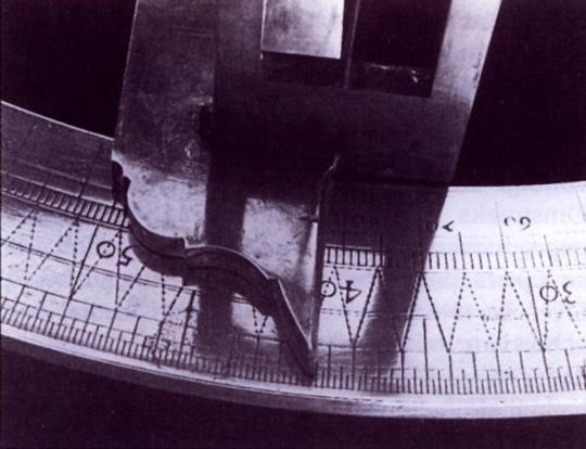
The first diagonal scales were made of zigzag lines around the scale.
Attached you will find a picture of such a diagonal scale on a Hollandse
Cirkel (a Dutch land survey instrument). This design is older than the
one we know from the Davis Quadrants and as you can see it leaves no
room for the option George suggests. Then that new design came up and
the basic principle stayed the same: the diagonals on the scale and the
reading edge straight.

2) It was not done because a straight edge was needed anyway
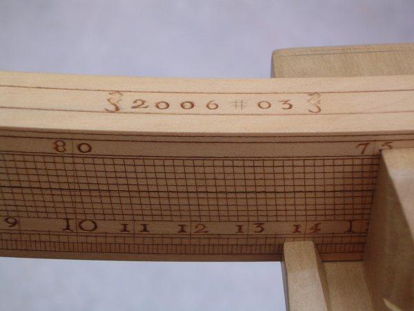
Attached you will also find a detailed picture one of the Davis
Quadrants I made. The diagonals are clearly visible and on the right is
the inner side of the sight vane with the straight edge that was needed
to take the readings. As you can see along the lower edge of the scale
there is a 'normal' perpendicular scale divided into 5 arc minutes
intervals. For that part one would need a perpendicular edge to read it
(like there is on this sight vane). So in order to combine the two one
had to make a kink in the edge so that the lower part would be
perpendicular and the upper part diagonal. The diagonal then would have
to point to the right to make it possible to read the scale, but that
would also add to the confusion as the diagonal would read ahead of the
scale. One could make it the other way around as well (so mirroring the
whole vane design) but then the diagonal would seem to read behind of
the actual value.

3) It was not done because of alignment problems
Lets suggest we would have made the scale as in 2). Any wear of the
inner side of the vane, or outside of the scale would let the diagonal
of the vane move inwards towards the centre of the instrument. As a
result of this the readings will not be correct any more.
Another thing is that when constructing the Davis Quadrant the arc is
sawn from a piece of wood. The shape is drawn onto it using a beam
compass, but there is no 'centre of the instrument' as yet, only the
diameter is known. Then the whole frame is constructed and the
instrument gets its centre, which is a small hole drilled into the main
beam on the observer side of the horizon vane (the surface of the
horizon vane is the centre of that hole). Small errors made during the
construction phase of the frame will result into a misalignment of the
outside of the arc and the centre of the instrument. As long as this
error is small it will not affect the readings of the diagonal scale
(when made as we know it). The concentric circles will not be completely
parallel to the outside of the arc, but that can be compensated by
tilting the vane until the edge aligns with the scale (something that
has to be done anyway, regardless the quality of the concentricity).
What does change is the distance between the concentric circles and the
outside of the scale. So if constructed the way George proposed the
diagonal would be in the proper position at one end of the scale, but
not when on the other end of the scale and therefore introducing errors.

At the end this post has become somewhat larger than expected....

Nicolàs


--~--~---------~--~----~------------~-------~--~----~
To post to this group, send email to NavList@fer3.com
To , send email to NavList-@fer3.com
-~----------~----~----~----~------~----~------~--~---
