NavList:
A Community Devoted to the Preservation and Practice of Celestial Navigation and Other Methods of Traditional Wayfinding
Polhemus computer
From: UNK
Date: 2008 Jul 15, 04:12 -0700
From: UNK
Date: 2008 Jul 15, 04:12 -0700
Gary LaPook writes:

The Polhemus computer provides a convenient way  to plot celnav fixes
and this posting will show how you use it for this purpose. The other
side of the computer is used for in flight celnav and I will leave a
discussion of that use for later.

The first step in plotting a celnav fix is plotting the assumed
positions for each body and I will use the data from the "3-Star
Fix-'Canned Survival  Problem'" thread for this example.

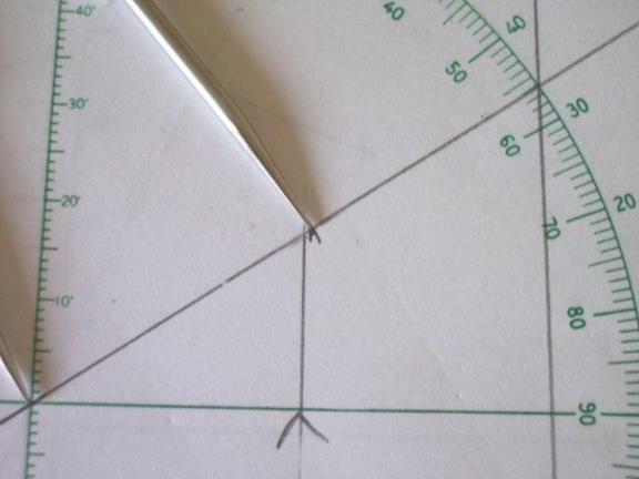
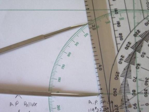
Figure 1 shows the standard way of making a plotting sheet. A line is
drawn from the center at the same angle above above the horizontal that
is the same as the latitude of the center of the plotting sheet, in this
case, 34 degrees. The dividers are set to the difference in longitude
from the center meridian (in this case 119º 15') to the longitude of the
A.P. The first A.P. plotted is for Vega which is 119º 06.9' which is
7.9' east of the center meridian so the dividers are set to represent
7.9 as measured on the center meridian scale which I have multiplied
four times to make the scale of the plotting sheet larger so the
dividers were set to 31.6 and placed along the diagonal line. From this
point you go straight down and place the mark for the A.P. (an inverted
"V") on the central parallel of latitude.

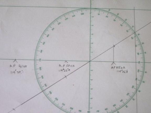
 Figure 2 shows the other two A.P.s plotted as well.

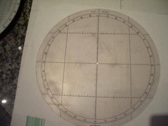
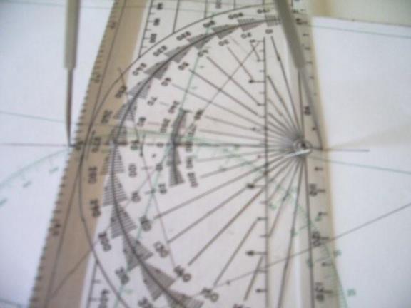
Figure 3 shows the base of the Polhemus computer which a vertical grid
marked in units, an unmarked horizontal grid and a surrounding azimuth
scale. ( On my computer I have added two scales near the center of the
grid for calculating the "motions" for in flight use and these scales
should be disregarded for this discussion..)

Figure 4 shows the transparent plotting surface that is mounted on the
central pivot of the base which has three vertical and three horizontal
lines lines forming a square and spaced to occupy 15 units on the
vertical scale on the base unit. (The plotting surface also has scales
marked along the lines but we will not make use of these tic marks.)

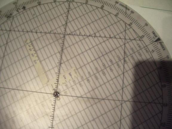
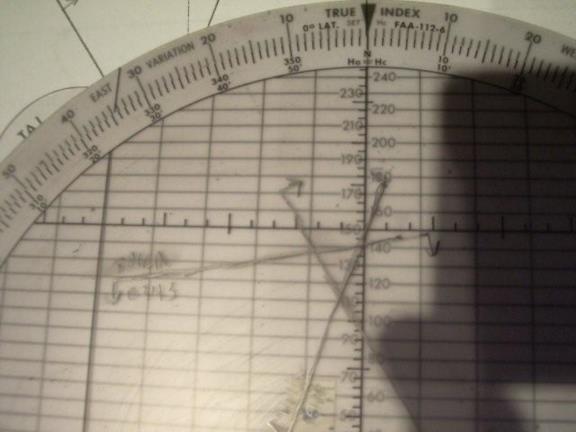
Figure 5 shows the plotting disk mounted on the base with the true index
set at 56º which lines up the numbered central line on the base 34º
above the horizontal and this causes the computer to be set in the
equivalent manner as the plotting sheet in figure 1. We use a similar
procedure and go straight down from 7.9 on the scale and place the Vega
A. P. on the horizontal line.

Figure 6 show the the other A.P.s plotted with the A.P. for Spica
plotted up from 7.9 since the A.P. is 119º 22.9 which is 7.9 west of the
center meridian; and Pollux plotted up from 24.1 representing 119º 39.1'.

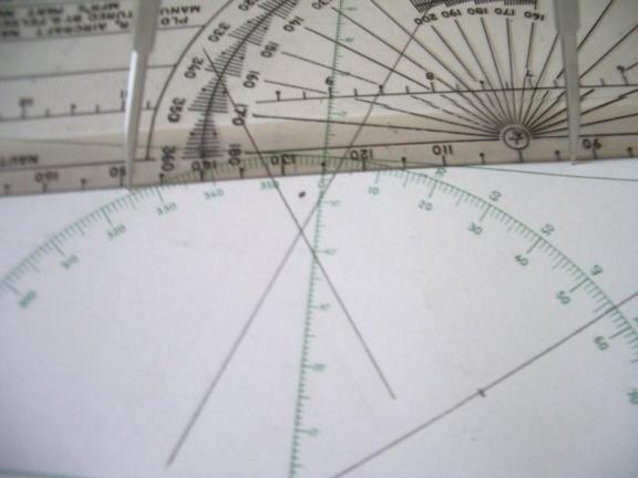
Figures 7 through 12 show the plotting of the Spica line on the plotting
sheet using an aircraft plotter and the '"flip-flop" method. Figure 7
shows the plotter's edge passing through the Spica A.P. and set to the
azimuth of 170.5º, the azimuth of Spica.

Figure 8 shows the dividers set to a scaled intercept of 12.9 NM and set
along the straight edge with one leg on the A.P.. Holding the dividers
in place the the plotter is slid up so that the 270º mark on the plotter
scale is against the other leg of the dividers which is shown in figure 9.

Now carefully holding that leg and the plotter in place you move the leg
that had been at the A.P. so that is is on the reference line on the
other side of the azimuth scale on the plotter so that now the dividers
is at right angles to its previous position as shown in figure 10.

Carefully holding the dividers in place you slide the plotter out and
reposition it with the straight edge against the two divider legs so now
the straight edge is in position to draw the Spica LOP as shown in
figure 11 and 12.

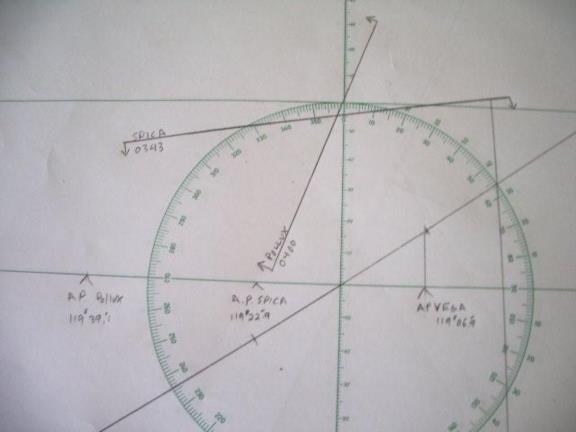
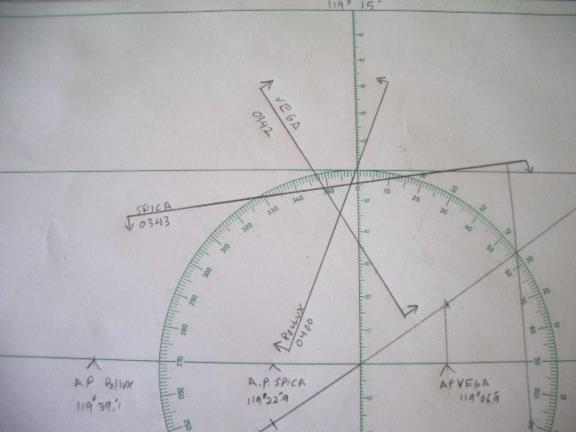
Figure 13 shows the complete fix after carrying out the same steps for
the other bodies.

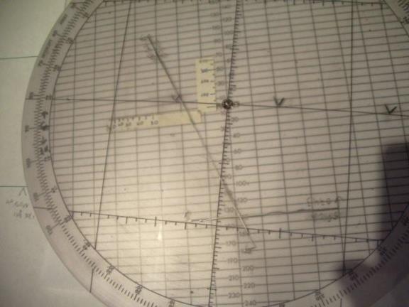
We will now go through the same process on the Polhemus computer. Figure
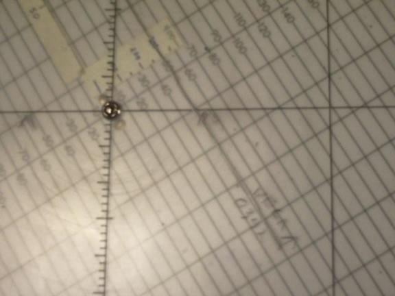
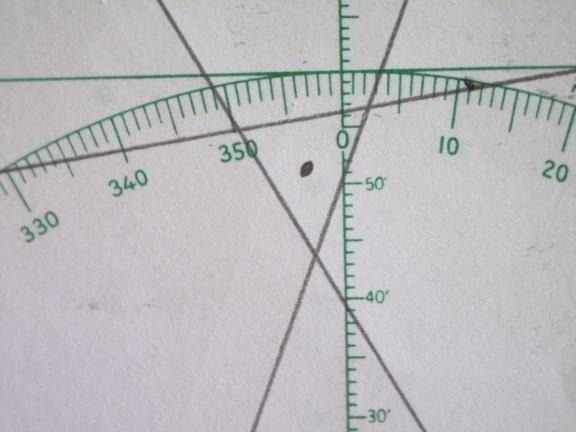
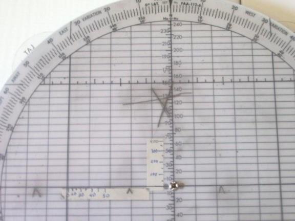
14 shows the true index set to 58º which is the azimuth of Vega. Figure
15 shows the A.P. for Vega which is at 5.5 on the base grid. Since the
Vega intercept is .5 away we move away from 58º half of a NM and trace
the LOP on top of the "5" grid line as shown in figures 15 and 16.


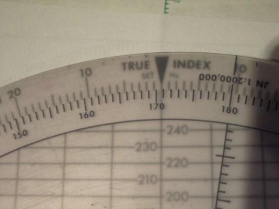
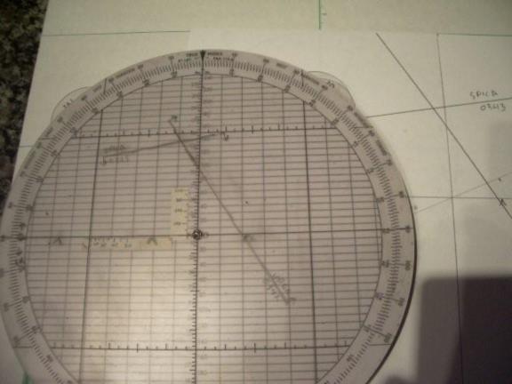
Figure 17 shows the true index set to 170.5º which is the azimuth of
Spica. We then count down (away) 12.9 NM from the Spica A.P. (which is
the "V" located on the "1" grid line, actually the "10" line which we
are scaling as "1") and trace the Spica LOP on top of the "14" line as
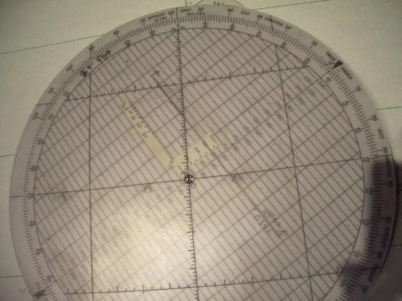
shown in figure 18. Figure 19 shows the Vega and Spica LOPs with the
plotting disk set to show north as up.
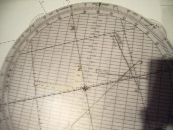
Figure 20 shows using the same procedure being used to plot the Pollux
line with an intercept of 13.6 away from an azimuth of 290º.

Figure 21 shows the completed fix with the plotting disk set to north up.

After carefully plotting these two examples I decided to go for "time."
I started over again with a fresh plotting sheet and an erased Polhemus
plotting disk. It took 2 minutes and 10 seconds to plot the three A.P.s
on the plotting sheet; an additional 1 minute 25 seconds to plot the
Vega LOP; an additional 1 minute 30 seconds to to plot the spica LOP; 58
seconds more to plot the Pollux LOP and finally another 40 seconds to
derive the fix for a total time of 6 minutes and 45 seconds. The fix is
34º 13'N, 119º 16.5' W. This is shown in figures 22 and 23.

I then did the same exercise on the Polhemus computer. It took 22
seconds to plot the three A.P.s; 40 seconds to plot the first LOP; 28
seconds for the second LOP; 18 seconds for the third LOP; then 41
seconds to derive the fix for a total of just 2 minutes and 29 seconds
which is 4 minutes and 16 seconds faster than using the traditional
plotting sheet. The fix is 34º 12.5'N, 119º 16' W a half  mile south and
a half mile east of the fix as plotted on the traditional plotting
sheet. This is shown in figures 24 and 25.

gl


--~--~---------~--~----~------------~-------~--~----~
Navigation List archive: www.navlist.net
To post, email NavList@navlist.net
To , email NavList-@navlist.net
-~----------~----~----~----~------~----~------~--~---
